
This year, we launched an all-new version of our Kingfisher surface vessel. Like many ROS robots, its onboard linux PC is supplemented with a microcontroller, which handles low-level tasks like monitoring ADCs and driving motors. When prototyping the new Kingfisher we used the Atmega 32U4 Microcontroller and Arduino IDE.
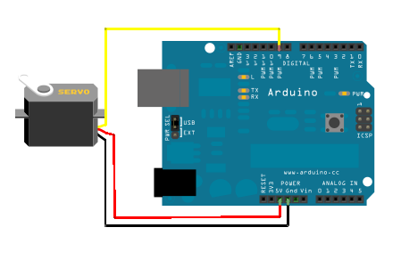
This is the basic idea:

We’ve found that it’s best for the microcontroller firmware in these situations to be as simple as possible—concentrating control logic on the PC makes the overall system much easier to observe and debug, and less code means reduced likelihood of needing to reprogram the device in response to errors, hardware changes, etc.
One of the key ways to keep complexity on the microcontroller down is by taking advantage of the rosserial library to handle communication with the rest of ROS. Rosserial allows the firmware to deal directly in ROS topics and services, and avoids one-off serial protocols and associated translation nodes on the PC. We use rosserial with many of our products, including Kingfisher.
We’ll probably have a handful of articles with some further tips about using microcontrollers with ROS, but for the remainder of this piece, I just want to give a quick hint about delivering reliable servo pulses from an Atmega 32U4 microcontroller.
The Servo library for Arduino creates servo pulses using the Timer1 interrupt handler. Unfortunately, on USB-capable AVRs like the 32U4, the USB interrupts have priority 11 and 12, while Timer1’s interrupts start at priority 18. Unlike some other microcontrollers, the AVR’s interrupt priorities are not configurable. What this means is, when the USB interrupt handler is busy receiving or sending serial traffic, servo pulses get stretched and distorted, resulting in weirdly spazzy motor behaviour.
To achieve reliable operation, it’s best to stay away from the standard Arduino Servo library, and instead drive PWM pins using the AVR’s hardware PWM peripheral. This is not hard to do! In the Kingfisher firmware, we create servo pulses on pins PB5 and PB6 for the port and starboard drives. The setup is like so:
DDRD |= _BV(5) | _BV(6);
TCCR1A = _BV(COM1A1) | _BV(COM1B1) | _BV(WGM11);
TCCR1B = _BV(WGM13) | _BV(WGM12) | _BV(CS11) | _BV(CS10);
ICR1 = 4999;
You can look up these registers in the datasheet (PDF) to figure out exactly what’s going on here, but the long and short of it is that this sets us up for a PWM configuration on the Timer1 peripheral, with a prescaler of 64 from the main 16MHz clock. With the ICR1 value as specified, this timer has a period of 20ms (for a standard 50Hz pulse).
Servo pulses vary in length from 1ms to 2ms. The specific interpretation of this varies from device to device, but with our drivers, that’s full reverse to full forward, with a neutral point at 1.5ms. In the timer configuration given above, the two output pins may be controlled in the servo range by setting OCR1A or OCR1B to a value between 249 (for 1ms) and 499 (for 2ms).
The USB interrupts will still take higher priority, but this approach is no longer sensitive to the timing of software interrupt handlers—it all happens in the background, in the hardware peripheral. This method can be used with motor controllers like the Parallax HB-25, Sabertooth units, and many others. Of course, it can also be used with hobby servos, for controlling steering arms, pan-tilts, and endless other applications.
Trackbacks/Pingbacks