Navigation
Features
The OutdoorNav Software contains a set of features that can be enabled or disabled according
to your required application requirements. These features can be enabled or disabled through
the use of environment variables, which should be added to the /home/administrator/cpr_outdoornav_launch/outdoornav_tuning.env.
The following table describes the available features, their default state and any additional
parameters that we expose that may also be included to tune the feature.
Feature |
Description |
|---|---|
Data Collection |
The data collection feature enabled the user to record rosbag data of the sensors, localization, and navigation components of OutdoorNav. If Environment Variable: |
Collision Avoidance |
Collision avoidance is the UGV’s ability to detect obstacles and stop/maneuver around the
obstacle without any collisions. If Environment Variable: |
Obstacle Avoidance Mode |
When collision avoidance is enabled, the UGV will behave in one of two ways according to the
obstacle avoidance mode. If set to Environment Variable: |
Continuous Planning |
The continuous planning feature allows the UGV to continuously monitor whether an obstacle is on the UGV’s path and replan around said obstacle smoothly without the need for stopping in front of the obstacle. If disabled, the UGV will come to a full stop in front of an obstacle and then replan around said obstacle. Environment Variable: |
Path Smoothing |
The path smoothing feature allow paths to be generated according to a specified turning radius. The default behaviour will generate point-to-point straight line paths. Environment Variable: |
Path Shifting |
The path shifting feature is designed to reduce the oscillation around the initial reference path if the UGV begins to deviate of said reference path. It is particularly useful for the Clearpath Robotics Warthog platform whose tires are incredibly pliable and results in unmodelled effects on the navigation. Environment Variable: |
Constrained Replanning |
The constrained replanning feature restricts the area in which replanning paths can be generated.
For example, if a Environment Variable: Use the |
Stop Distance |
The stop distance feature allows the UGV to stop a predefined distance away from obstacles. This is useful if a UGV cannot drive in reverse and needs the required room in front of it to replan around an obstacle. Environment Variable: Use the |
Delay Compensation |
The delay compensation feature is able to compensate for mechanical delay on UGVs where either the accelerator introduces delay into the linear velocity or the steering introduces delay in the angular velocity. This feature is not required for Clearpath Robotics UGVs as negligible delay is present in our system. Environment Variable: Use the |
Advanced Configuration
The following section provides a list of environment variables that can be modified in order to tune both the sensor systems as well as tuning the navigation software. All of the environment variables listed below can be modified in the /home/administrator/cpr_outdoornav_launch/outdoornav_tuning.env file.
Sensor Tuning
The following table lists the sensors that are useable with the OutdoorNav software. These sensor drivers can be turned on/off using these environment variables, however, the sensor will always remain powered on.
Environment Variable |
Description |
Data Type |
|---|---|---|
SWIFTNAV_ENABLE_DRIVER |
Enable/disable the Swiftnav Piksi/Duro ROS driver, if integrated. |
bool |
UBLOX_ENABLE_DRIVER |
Enable/disable the UBlox ROS driver, if integrated. |
bool |
MICROSTRAIN_ENABLE_DRIVER |
Enable/disable the Microstrain GX5/CV5 ROS driver, if integrated. |
bool |
XSENS_ENABLE_DRIVER |
Enable/disable the XSens MTI ROS driver, if integrated. |
bool |
VLP_ENABLE_DRIVER |
Enable/disable the Velodyne ROS driver, if integrated (front unit if more than one). |
bool |
REAR_VLP_ENABLE_DRIVER |
Enable/disable the Velodyne ROS driver, if integrated (rear unit if more than one). |
bool |
LMS1XX_ENABLE_DRIVER |
Enable/disbale the Sick LMS1XX ROS driver, if integrated (front unit if more than one). |
bool |
REAR_LMS1XX_ENABLE_DRIVER |
Enable/disbale the Sick LMS1XX ROS driver, if integrated (rear unit if more than one). |
bool |
HOKUYO_ENABLE_DRIVER |
Enable/disbale the Hokuyo ROS driver, if integrated (front unit if more than one). |
bool |
REAR_HOKUYO_ENABLE_DRIVER |
Enable/disbale the Hokuyo ROS driver, if integrated (rear unit if more than one). |
bool |
D435_ENABLE_DRIVER |
Enable/disable the Realsense ROS driver, if integrated (front unit if more than one). |
bool |
REAR_D435_ENABLE_DRIVER |
Enable/disable the Realsense ROS driver, if integrated (rear unit if more than one). |
bool |
Sensor Tuning (Advanced)
The following list of environment variables can be used to filter the sensor data in order to modify/improve the sensory input to the OutdoorNav autonomy. It is recommended that you first consult the following links before attempting to modify these parameters.
Voxel Grid Filter
Environment Variable |
Description |
Data Type (Default) |
|---|---|---|
<type>_ENABLE_FILTER_VOXEL |
Enable/disable the PCL voxel filter for the sensor of type <type>. type = {VLP, D435, REAR_VLP, REAR_D435} |
bool (false) |
PCL_FILTER_VOXEL_LEAF_SIZE |
The size of a leaf (on x,y,z), in meters, used for downsampling. Range: 0.0 to 1.0. |
double (0.01) |
Cropbox Filter
Environment Variable |
Description |
Data Type (Default) |
|---|---|---|
<type>_ENABLE_FILTER_CROPBOX |
Enable/disable the PCL cropbox filter for the sensor of type <type>. type = {VLP, D435, REAR_VLP, REAR_D435} |
bool (false) |
PCL_FILTER_CROPBOX_MIN_X |
The lower bound, in meters, on the x-axis within which to reject points from the pointcloud. Range: -1000.0 to 1000.0. |
double (0.01) |
PCL_FILTER_CROPBOX_MAX_X |
The upper bound, in meters, on the x-axis within which to reject points from the pointcloud. Range: -1000.0 to 1000.0. |
double (2.0) |
PCL_FILTER_CROPBOX_MIN_Y |
The lower bound, in meters, on the y-axis within which to reject points from the pointcloud. Range: -1000.0 to 1000.0. |
double (-10.0) |
PCL_FILTER_CROPBOX_MAX_Y |
The upper bound, in meters, on the y-axis within which to reject points from the pointcloud. Range: -1000.0 to 1000.0. |
double (10.0) |
PCL_FILTER_CROPBOX_MIN_Z |
The lower bound, in meters, on the z-axis within which to reject points from the pointcloud. Range: -1000.0 to 1000.0. |
double (-0.5) |
PCL_FILTER_CROPBOX_MAX_Z |
The upper bound, in meters, on the z-axis within which to reject points from the pointcloud. Range: -1000.0 to 1000.0. |
double (10.0) |
Radius Outlier Filter
Environment Variable |
Description |
Data Type (Default) |
|---|---|---|
<type>_ENABLE_FILTER_RADIUS_OUTLIER |
Enable/disable the PCL radius outlier filter for the sensor of type <type>. type = {VLP, D435, REAR_VLP, REAR_D435} |
bool (false) |
PCL_FILTER_ROR_RADIUS_SEARCH |
The number of points within this distance, in meters, from the query point will need to be equal or greater than PCL_FILTER_ROR_MIN_NEIGHBORS in order to be classified as an inlier point (i.e. will not be filtered). |
double (0.05) |
PCL_FILTER_ROR_MIN_NEIGHBORS |
The number of points within PCL_FILTER_ROR_RADIUS_SEARCH from the query point will need to be equal or greater than this number in order to be classified as an inlier point (i.e. will not be filtered). |
int (10) |
Statistical Outlier Filter
Environment Variable |
Description |
Data Type (Default) |
|---|---|---|
<type>_ENABLE_FILTER_STATISTICAL_OUTLIER |
Enable/disable the PCL statistical outlier filter for the sensor of type <type>. type = {VLP, D435, REAR_VLP, REAR_D435} |
bool (false) |
PCL_FILTER_SOR_MEAN_K |
The number of points (k) to use for mean distance estimation Range: 2 to 100. |
double (5.0) |
PCL_FILTER_SOR_STD_DEV |
The standard deviation multiplier threshold. All points outside the mean +- sigma * std_mul will be considered outliers. Range: 0.0 to 5.0. |
double (0.3) |
PointCloud to LaserScan Filter
Environment Variable |
Description |
Data Type (Default) |
|---|---|---|
<type>_ENABLE_POINTCLOUD_TO_LASERSCAN |
Enable/disable the pointcloud to laserscan outlier filter for the sensor of type <type>. type = {VLP, D435, REAR_VLP, REAR_D435} |
bool (false) |
PCL_TO_SCAN_MIN_HEIGHT |
The minimum height to sample in the point cloud, in meters. |
double (0.2) |
PCL_TO_SCAN_MAX_HEIGHT |
The maximum height to sample in the point cloud, in meters. |
double (1.2) |
PCL_TO_SCAN_MIN_ANGLE |
The minimum scan angle, in radians. |
double (3.14) |
PCL_TO_SCAN_MAX_ANGLE |
The maximum scan angle, in radians. |
double (3.14) |
PCL_TO_SCAN_ANGLE_INCREMENT |
Resolution of laser scan, in radians, per ray. |
double (0.00218) |
PCL_TO_SCAN_TIME |
The scan rate in seconds. |
double (0.3333) |
PCL_TO_SCAN_MIN_RANGE |
The minimum ranges to return, in meters. |
double (0.3) |
PCL_TO_SCAN_MAX_RANGE |
The maximum ranges to return, in meters. |
double (100.0) |
DepthImage to LaserScan Filter
Environment Variable |
Description |
Data Type (Default) |
|---|---|---|
<type>_ENABLE_DEPTH_TO_LASERSCAN |
Enable/disable the depth image to laserscan outlier filter for the sensor of type <type>. type = {D435, REAR_D435} |
bool (false) |
DEPTH_TO_SCAN_HEIGHT |
The number of pixel rows to use to generate the laserscan. For each column, the scan will return the minimum value for those pixels centered vertically in the image. |
int |
DEPTH_TO_SCAN_TIME |
Time between scans (seconds). Typically, 1.0/frame_rate. This value is not easily calculated from consecutive messages, and is thus left to the user to set correctly. |
double |
DEPTH_TO_SCAN_MIN_RANGE |
The minimum ranges to return in meters. Ranges less than this will be output as -Inf. |
double |
DEPTH_TO_SCAN_MAX_RANGE |
The maximum ranges to return in meters. Ranges greater than this will be output as +Inf. |
double |
Command Line Operation
By default the OutdoorNav Software, including the Navigation component, begins automatically when the system is powered on. This section outlines the commands that can be used by developers who are debugging the system or who want more precise control for managing the Navigation component.
Stopping/Restarting the Autonomy
To use the UGV without the autonomy core of OutdoorNav, use these commands to stop the nodes and prevent them from automatic startup:
cd ~/cpr_outdoornav_launch/ # directory with docker-compose.yaml
docker compose --profile autonomy stop
The autonomy core can be restarted by running:
cd ~/cpr_outdoornav_launch/    # directory with docker-compose.yaml
docker compose --profile outdoornav start
Stopping/Restarting the Sensors
To use the UGV without the sensors, use these commands to disable the nodes and prevent them from automatic startup:
cd ~/cpr_outdoornav_launch/    # directory with docker-compose.yaml
docker compose stop
Accessing the Shell in Docker Container
To access the shell in a Docker container for debugging (optionally replace onav-autonomy with
onav-web in the following command):
cd ~/cpr_outdoornav_launch/      # directory with docker-compose.yaml
docker compose exec -it onav-autonomy bash
Validating TF Setup
Note
Sensor TF validation should only be required if the performance is noticeably poor, such as when the UGV drifts off of the planned path or oscillations occur around the path).
The coordinate transformation of the two GPS antennas, the IMU, the 2D and 3D Lidars to the base_link of the UGV should have already been set prior to receiving the UGV. However, ensure that they are set correctly.
The ROS coordinate frame base_link, shown in the figure below, is located at the center of the bottom plate of the UGV. The environment variables below should be taken with respect to this coordinate frame. The X axis is in red (and pointing towards the front of the UGV), Y in green (pointing towards the left of the UGV) and Z in blue (pointing towards the sky).
You can check the current value of the environment variables by running the following (and setting <variable_name> to the names listed in the table below).
printenv | grep <variable_name>
The environment variables for the position and orientation of each sensor are provided in the table below.
Environment Variable |
Function |
|---|---|
POSITION_GPS_XYZ |
[X,Y,Z] position, in meters, of the position (rear) GPS antenna with respect to the base_link coordinate frame |
POSITION_GPS_RPY |
[Roll,Pitch,Yaw], in radians, of the position (rear) GPS antenna with respect to the base_link coordinate frame. |
HEADING_GPS_XYZ |
[X,Y,Z] position, in meters, of the heading (front) GPS antenna with respect to the base_link coordinate frame. |
HEADING_GPS_RPY |
[Roll,Pitch,Yaw], in radians, of the heading (front) GPS antenna with respect to the base_link coordinate frame. |
MICROSTRAIN_XYZ |
[X,Y,Z] position, in meters, of the IMU with respect to the base_link coordinate frame. |
MICROSTRAIN_RPY |
[Roll,Pitch,Yaw], in radians, of the IMU with respect to the base_link coordinate frame. |
LIDAR_XYZ |
[X,Y,Z] position, in meters, of the 3D Lidar with respect to the base_link coordinate frame. |
LIDAR_RPY |
[Roll,Pitch,Yaw], in radians, of the 3D Lidar with respect to the base_link coordinate frame. |
LASER_XYZ |
[X,Y,Z] position, in meters, of the 2D Lidar with respect to the base_link coordinate frame. |
LASER_RPY |
[Roll,Pitch,Yaw], in radians, of the 2D Lidar with respect to the base_link coordinate frame. |
Note
When the printed Y axis on the IMU is pointing towards the front of the robot (i.e., aligned to X axis of base_link), MICROSTRAIN_RPY = [0, 0, 0].
Warning
If you decide to move any of these sensors, you must modify these variables accordingly.
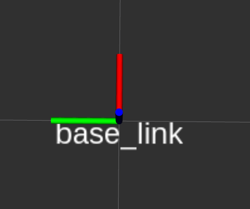
base_link coordinate frame