Interface Control Requirements
Interface Control Checklist
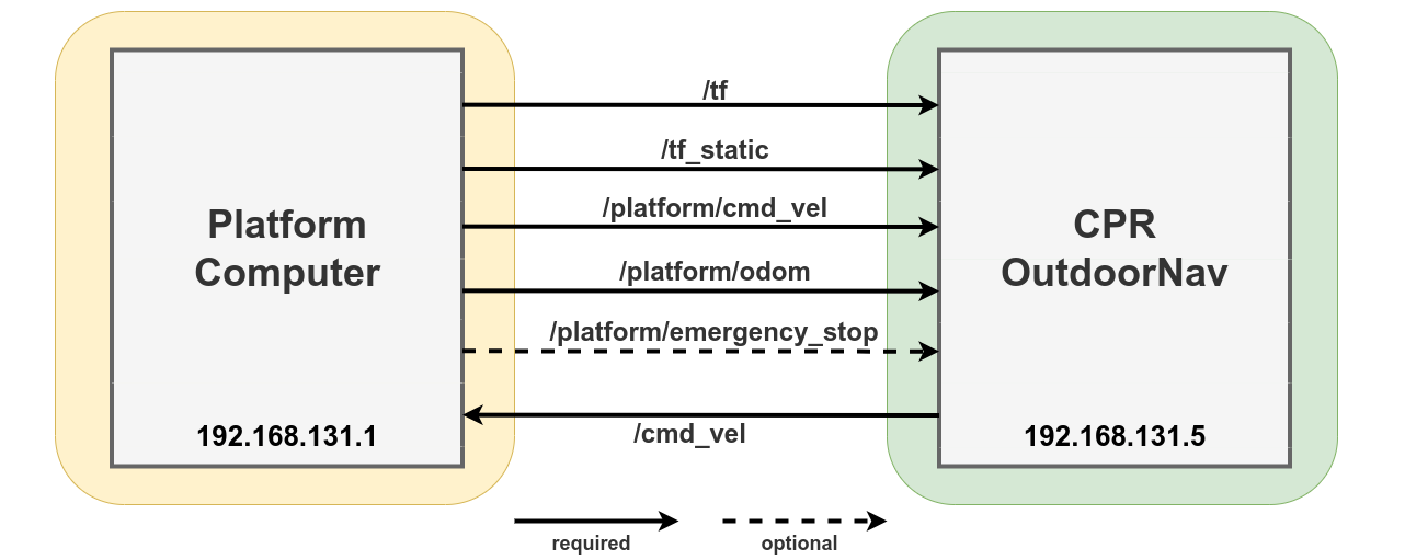
Prior to the installation and tuning of Clearpath Robotics (CPR) OutdoorNav software on your platform, CPR requires that the platform satisfy the conditions listed below. Ensure that all of the requirements are satisfied for a smooth installation and tuning process.
Requirement |
|
|---|---|
The platform computer is on the 192.168.131.xxx subnet (ideally in the range 1-4). |
|
The platform computer has an installation of ROS1 Noetic. |
|
A URDF is supplied to CPR by the customer, in which the |
|
The platform outputs tf2_msgs/TFMessage messages on the ROS standard |
|
The platform outputs a latched tf2_msgs/TFMessage message on the ROS standard |
|
The OEM platform outputs nav_msgs/Odometry messages on the |
|
The odometry topic publishes the odom → base_link transformation as per the REP-105 odom ROS standard. |
|
The platform odometry output has less than ±5% linear position error. |
|
The platform odometry output has less than ±5% orientation error. |
|
The platform computer has a velocity controller that accepts geometry_msgs/Twist messages on the ROS standard |
|
The platform computer has a velocity controller that tracks the input velocity and outputs the resulting platform velocity on the |
|
The platform outputs std_msgs/Bool messages on the |
|
Perform the validation tests described in Interface Control Validation Test and record a rosbag of all of your topics. The linear and angular velocities of the three trial runs recorded should be noted here:
Trial #1: Linear x: , Angular z:
Trial #2: Linear x: , Angular z:
Trial #3: Linear x: , Angular z:
|
Note
Consult the Platform API for detailed information on the published/subscribed platform topics.
If the platform is an Ackermann (or double Ackermann) drive vehicle:
Requirement |
|
|---|---|
A conversion from geometry_msgs/Twist messages to Ackermann inputs is provided. |
Note
Ackermann drive platforms require both steering and throttle inputs to drive the platform. It is required that our OutdoorNav output
/cmd_vel be converted into a message suitable to your platform. An example of an Ackermann message type can be found
here. This may satisfy your particular platform,
and is only a starting point on how to do this conversion.
If the platform computer is running a version of ROS2:
Requirement |
|
|---|---|
The platform computer has a ROS2 to ROS1 bridge is installed to enable the exchange of messages between the two ROS versions. |
Signature: Date:
Interface Control Validation Test
The following test is designed to validate the platforms velocity controller. It will be required that you command the robot to drive in three circles, of varying radii, by applying the following command to the platform.
rostopic pub -r 10 /cmd_vel geometry_msgs/Twist "linear:
x: ___
y: 0.0
z: 0.0
angular:
x: 0.0
y: 0.0
z: ___"
The three trials that we request will vary between platforms depending on the its maximum linear \((v_{max})\) and angular velocities \((\omega_{max})\), minimum linear \((v_{min})\) and angular velocities \((\omega_{min})\), as well as limitations due to the minimum allowable turning radius \((r_{min})\). Of these three trials, we would like to see data within three linear velocity bands, as seen in the table below, resulting in three different turning radii. For the purpose of these tests the followng formula can be used when determining the required linear and angular velocities to apply: \(r = v/\omega\).
Trial # |
Linear X Bands [m/s] |
Example Linear X Band [m/s] |
|---|---|---|
1 |
\(v_{min} \cdot [1.0, 1.5]\) |
\([0.5, 0.75]\) |
2 |
\(((v_{max} - v_{min})/2) \cdot [0.9, 1.1]\) |
\([2.025, 2.475]\) |
3 |
\(v_{max} \cdot [0.9, 1.0]\) |
\([4.5, 5.0]\) |
As an example, a platform with specs \(v \in [0.5, 5.0]\), \(r_{min} = 3\) would have linear x velocity bands as listed in the table above. The trials could then be as outlined in the table below.
Trial # |
Linear X [m/s] |
Angular Z [rad/s] |
Turn Radius [m] |
|---|---|---|---|
1 |
0.75 |
0.25 |
3 |
2 |
2.25 |
0.5 |
4.5 |
3 |
4.5 |
0.75 |
6 |
Finally, the test data in the collected ROSbag should include the following:
/tfand/tf_static/platform/cmd_vel/platform/odom/cmd_vel/platform/emergency_stop(if available)raw NavSatFix data from a GPS unit (if possible).