Clearpath Robotics Hardware
When using a Clearpath Robotics UGV and Base Station, the following hardware setup may be required.
Calibrating the IMU
Although IMU magnetometers are calibrated at the factory to remove any internal magnetic influences in the device, measurements are still subject to influence from external magnetic anomalies when the sensor is installed. These anomalies are divided into two classes: hard iron offsets and soft iron distortions. Hard iron offsets are created by objects that produce a magnetic field. Soft iron distortions are considered deflections or alterations in the existing magnetic field. Ideally, these influences are mitigated by installing the sensor away from magnetic sources, such as coils, magnets, and ferrous metal structures and mounting hardware. However, often these sources are hard to avoid or are hidden. To mitigate this effect when using the IMU magnetometer to aid in heading estimations, a field calibration of the magnetometer after final installation is highly recommended. This means that the IMU must be calibrated in the same environment that you use your UGV for autonomous navigation.
Microstrain IMU
If your UGV has a 3DM-GX5-25 Microstrain IMU, the complete instruction on calibration of your IMU can be found in section 5.4 of the datasheet. Note that you need a computer with Windows system and the LORD Sensing MIP Hard and Soft Iron Calibration software installed which can be found at the Microstrain website.
UM6/7 IMU
If you are using UM6 or UM7 IMUs, you will need the magnetometer display package which is located at
the following address on your UGV:
/home/administrator/catkin_ws/Drivers/src/imu_tools/magnetometer_display.
Follow these steps to calibrate the IMU on your machine:
Create a catkin workspace on your local machine and copy the package
magnetometer_displayinto your src folder. Build this package with thecatkin_makecommand.Perform the following command to make the calibration script executable:
$ sudo chmod +x calibration.py
Connect the IMU to your computer and launch the driver. Or if you are on the same network as your UGV, make your UGV the ROS master and ensure that you can echo the IMU topic on your computer.
Open the
magnetometer.launchfile in themagnetometer_displaypackage and change the sections shown in the figure below. Specifically, setuse_mag_fieldto true when the IMU is outputting magnetometer measurements with asensor_msgs/MagneticFieldmessage, otherwise set to false. Microstrain is the only IMU which uses the MagneticField message type.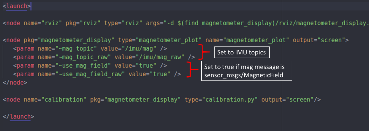
Magnetometer calibration, general launch settings
Launch the calibration using the following command:
$ roslaunch magnetometer_display magnetometer.launch
Move the IMU around to get good coverage. RViz will display magnetometer points (red) and will plot current ellipsoid fit (green) as shown in the figure below.
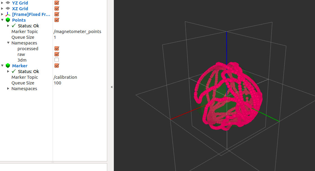
Magnetometer calibration, ellipsoid fit plot
Ellipsoid fit parameters are displayed in terminal as shown in the figure below.
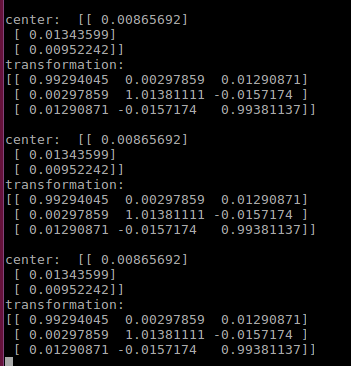
Magnetometer calibration, ellipsoid fit parameters
Once there are enough red points on your fitted ellipsoid, enter the above calibrations in the IMU driver launch file. Open the
sensor.launchfile in thecpr_gps_localizationpackage and go to the UM7 (or UM6) section of the launch file. The figure below shows this section for the UM7.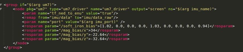
Magnetometer calibration, ellipsoid fit settings in launch file
You should enter the parameters generated in the Ellipsoid fit step as follows (to account for the NED to ENU transform the driver applies):
Launch file X = Terminal Y
Launch file Y = Terminal X
Launch file Z = -Terminal Z
RTK Positioning GPS Setup
Note
Please skip this section if your robot does not have RTK GPS.
The following configuration is for establishing communications between the Base Station and the UGV using TCP/IP for the purpose of transmitting RTK corrections. Before starting this procedure, make sure that you have installed the SwiftNav console.
Base Station GPS Configuration
Connect the Swift Navigation device to a computer via USB or the USB to Serial Adapter cable.
Open Swift Console and connect to the device.
Set the following options in the ethernet section as shown in the figure below.
ip_config_mode:
Staticip_address:
192.168.131.30netmask:
255.255.255.0
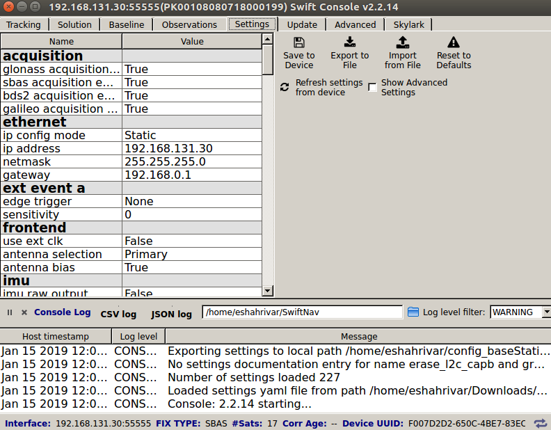
Base Station Ethernet settings
Set the following options in the tcp_server1 section as show in the figure below.
mode:
SBPport:
55556enabled_sbp_messages:
72,74,117,65535
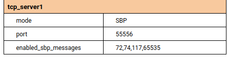
Base Station TCP1 Server settings
Set the following options in the solution section as shown in the figure below.
soln_freq:
10correction_age_max:
30output_every_n_obs:
10dgnss_solution_mode:
Low Latency
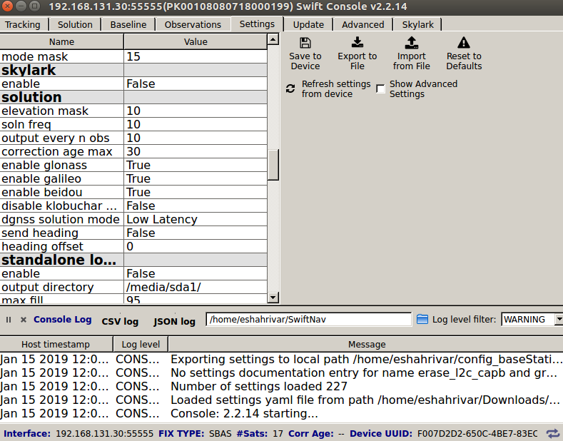
Base Station Solution settings
Next the Base Station has to be surveyed. There are two ways of doing this which are explained in RTK Survey Positioning.
Click Save to Flash.
Close Swift Console.
Disconnect the device from the computer.
UGV Position GPS Configuration
Connect the Swift Navigation device to a computer via USB or the USB to Serial Adapter cable.
Open Swift Console and connect to the device.
Set the following options in the ethernet section as shown in the figure below.
ip_config_mode:
Staticip_address:
192.168.131.31netmask:
255.255.255.0
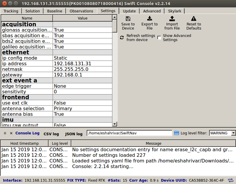
UGV GPS Ethernet settings
Set the following options in the tcp_client0 section as show in the figure below.
mode:
SBPport:
192.168.131.30:55556enabled_sbp_messages:
0
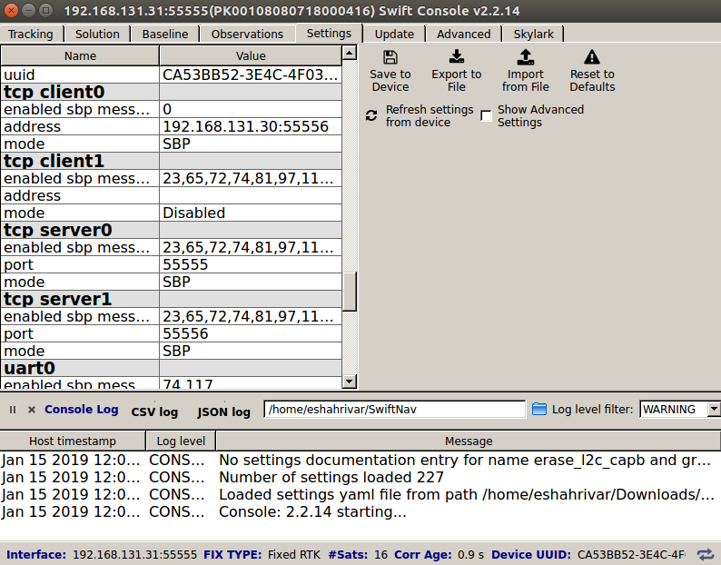
UGV GPS TCP Client0 settings
Set the following options in the solution section as show in the figure below.
soln_freq:
10correction_age_max:
30output_every_n_obs:
10dgnss_solution_mode:
Low Latency
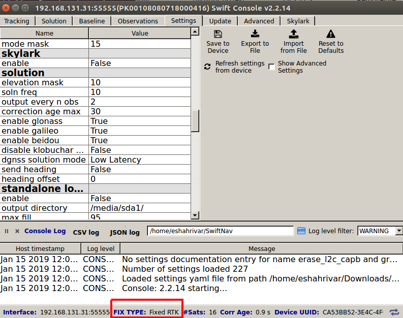
UGV GPS Solution settings
Click Save to Flash.
Close Swift Console.
Disconnect the device from the computer.
Once you have entered these settings. Connect your computer to the Wi-Fi network of the Base Station. Also make sure that the UGC (which is connected to the UGV GPS unit) is also connected to the Base Station Wifi. The you should be able to verify connectivity across the devices. To check the Base Station, complete the following steps.
Open Swift Console on you computer
Select TCP/IP
For IP Address enter
192.168.131.30For IP Port enter
55555Click OK
Select the Observations tab
In the Remote section you should see observation data from your UGV.
To check the UGV, complete the following steps.
Open Swift Console
Select TCP/IP
For IP Address enter
192.168.131.31For IP Port enter
55555Click OK
Select the Observations tab
In the Remote section you should see observation data from your Base Station.
Further information on RTK setup is available from SwiftNav.
RTK Survey Positioning
Note
Please skip this section if your UGV does not have RTK GPS.
Warning
Once you have surveyed the location of the Base Station, you cannot relocate the Base Station throughout your tests. Otherwise, this step has to be repeated.
There are three ways to survey the Base Station location:
OutdoorNav Web User Interface (easiest/accurate),
Swiftnav console autosurvey (fastest/least accurate),
ROS launch file geodetic survey (for debug output display).
Using the OutdoorNav Web UI is the easiest and most accurate way to do this since it runs the ROS geodetic survey tool which uses more samples to compute the final position of the Base Station than the Swiftnav console. Using the geodetic ROS survey launch file directly would allow the user to visualize the output log directly but requires preliminary knowledge in ROS.
Base Station Survey: Web UI
Using the OutdoorNav Web UI to survey the Base Station is very simple. See Survey Base Station for details.
Base Station Survey: Piksi Console
Use the Piksi console connect the base station GPS. Go to “Settings -> surveyed position”, click to any field in this section and then click the button on the top right corner “Auto Survey”. The figure below shows these steps. The last 1000 GPS points will be used to compute the position of the Base Station.
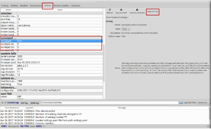
Auto Survey
After that, make sure the four fields in “surveyed position” (broadcast, surveyed lat, surveyed lon, surveyed alt) are consistent with your location.
Base Station Survey: ROS Geodetic Survey
The ethz_piksi_ros repository should be installed in the UGV’s catkin_ws.
To run the surveying process simply connect your PC to the Base Station network,
ssh into the UGV’s computer and run the following:
roslaunch {robot_name}_gps_navigation geodetic_survey.launch
where robot_name is either jackal, husky, or warthog depending on your
UGV. The surveying will begin and you will see a running tally of the collected data.
RTK Heading Setup
For the rest of this section, it is assumed that a third Swiftnav Duro device is available with IP address of 192.168.131.32. Note that in order to change the IP address of a Swiftnav Duro, you need to use the Swiftnav console and connect to the device with the serial port.
Note
The instructions in this section will overwrite some of the settings set in UGV Position GPS Configuration on the Position/Reference Duro receiver. This is normal since the configuration in UGV Position GPS Configuration is for a UGV with only the position Duro receiver. If the heading receiver is connected as well, please continue with the instructions below.
The two Swiftnav Duro GPS device on the UGV are connected via serial cable. They are also both connected via Ethernet cable to the computer on the UGV. For computing the heading, on Duro (the one on the rear with IP address 192.168.131.31) operates only to provide GNSS Observations to the other Duro that computes an RTK derived heading (the Duro on the front with IP address 192.168.131.32). For the purposes of this document, we will call the Duro/Piksi that operates to provide the raw GNSS observations only the “Reference Receiver” and the Duro/Piksi producing heading measurements the “Attitude Receiver.”
Use the Swiftnav console to connect to the Reference Receiver (with IP address of 192.168.131.31) and insert the settings shown in the figure below.
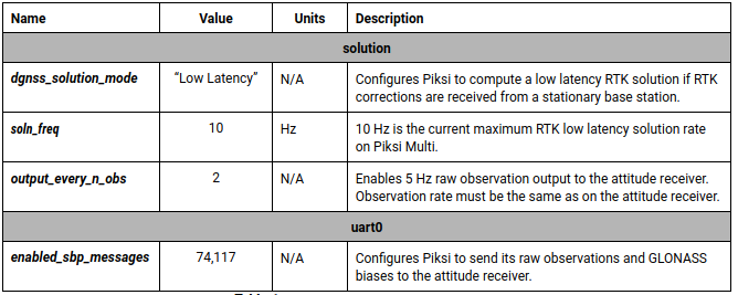
Reference Receiver settings
Next, connect to the Attitude Receiver (with IP address of 192.168.131.32) and change the configuration as shown in the figure below.
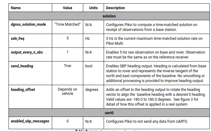
Attitude Receiver settings
For further information please refer to these instructions.
Wireless E-Stop
Please refer to the hardware user manual of the E-Stop device for proper usage. A trained operator should be used to supervise navigation of the UGV under autonomous control at all times. The Operator should be familiar with the use of the Wireless emergency stop device.