UGV Integration Requirements
Integration Overview
The scope of work to transform a non-autonomous UGV into an autonomous one will vary depending on the exact hardware capabilities and software interfaces of the UGV. Development work will be required by Clearpath Robotics, the end user, or a third party developer to bring the UGV into compliance with the requirements listed in the table below. This may involve implementing encoders and controllers to provide velocity control of the platform and implementing a CAN bus to ROS interface with kinematic control. The table below provides a general outline of the requirements; the detailed requirements are covered in the following sections.
# |
Task |
Note |
|---|---|---|
1 |
Convert platform to drive by wire |
If required; can be a significant electromechanical integration |
1.1 |
Implement actuated steering and throttle control if necessary |
|
1.2 |
Implement the encoder and controller hardware to provide wheel velocity control and odometry feedback |
May require electronic power steering position feedback and controller |
2 |
Create a ROS interface |
|
2.1 |
Commission an OutdoorNav computer running Ubuntu 20.04 and ROS Noetic |
|
2.2 |
Create a ROS interface to the UGV motor controllers and platform controller |
Often interfacing via CAN bus |
2.3 |
Create a ROS platform driver including UGV kinematics with ROS-control |
Accepts velocity input, commands motor controllers, provides other status feedback |
3 |
Install and configure OutdoorNav Hardware and Software |
|
3.1 |
Install OutdoorNav computer and sensors on the UGV |
Provide mechanical mounting, power and ethernet communication to UGV computer |
3.2 |
Install, update and configure OutdoorNav Software on computer |
Configure for sensor mounting locations, UGV kinematics and data topics. Can be done remotely with assistance from Clearpath Robotics Engineering. Approximately 1-2 days. |
3.3 |
Tune the path planning and following controllers for new UGV |
Can be done at a Clearpath Robotics facility. Can often be done at end user facility via remote login from Clearpath Robotics Engineering. Approximately 2-5 days. |
Hardware Integration Requirements
A UGV must meet all of the requirements below to enable integration with OutdoorNav Software.
UGV has a mounting point for the OutdoorNav Computer (recommendation: Vecow ECX-2000-9R)
UGV has electrical provisions for powering the OutdoorNav Computer.
UGV has a mounting point for a network switch (recommendation: TRENDnet TI-G80)
UGV has electrical provisions for powering the network switch
UGV has a mounting point for a forward-facing 3D lidar (recommendation: Velodyne VLP-16)
3D lidar can see objects 0.2 meters tall that are placed on the ground 1 meter in front of the UGV
The shadowing of 3D lidar’s view angles are acceptable by Clearpath Robotics Engineering.
UGV has electrical provisions for powering the 3D lidar
UGV has a mounting point for an attitude and heading reference system (recommendation: Microstrain 3DM-GX5-25 ). Note: Brackets between the AHRS and drive wheels should be stiff. The AHRS measures acceleration. Stiff brackets will ensure the measured acceleration is of the overall UGV, and not a vibration of the chassis.
UGV has mounting points for two GPS receivers (recommendation: Swift Navigation Duro)
UGV has mounting points for two GPS antennae (recommendation: Swift Navigation Antenna)
GPS antenna mount points are at least 700 millimeters apart.
GPS antennae are pointed +Z, toward the sky.
UGV has electrical provisions for powering both GPS receivers.
GPS antenna #1 has view angles that are not blocked by any parts on the UGV (±60°).
The shadowing of GPS antenna #1’s view angles are acceptable by Clearpath Robotics Engineering.
GPS receiver #1 has at least 6 satellite connections with a signal-to-noise ratio of at least 50 dB-Hz. Refer to “passing test” and “failing test” figures below.
GPS antenna #2 has view angles are not blocked by any parts on the UGV (±60°).
The shadowing of GPS antenna #2’s view angles are acceptable by Clearpath Robotics Engineering.
GPS receiver #2 has at least 6 satellite connections with a signal-to-noise ratio of at least 50 dB-Hz. Refer to “passing test” and “failing test” figures below.
UGV has a mounting point for a long range network client (recommendation: Microhard pX2).
UGV has electrical provisions for powering the long range network client.
UGV has a mounting point for a 2.4 / 5.8 GHz antenna.
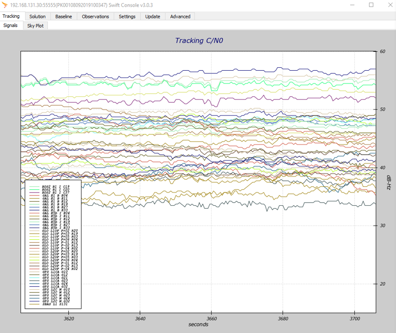
GPS receiver, signal-to-noise, passing test
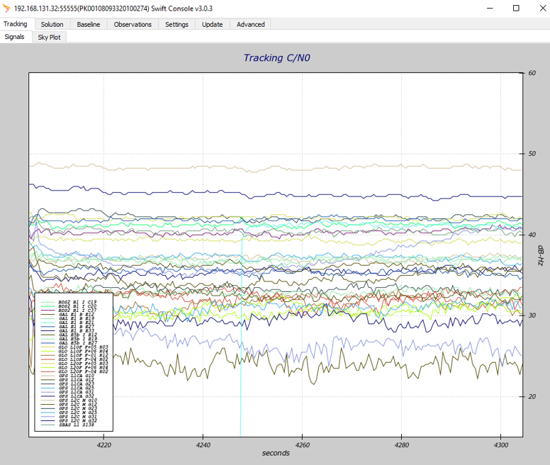
GPS receiver, signal-to-noise, failing test
Network Requirements
A UGV must meet all of the requirements below to enable integration with OutdoorNav Software.
The UGV’s controller (eg. x86 computer or ARM microcontroller) is running Linux and is configured with ROS Noetic.
The UGV’s controller shall have an RJ45 Ethernet port configured to the static address
192.168.131.1and subnet255.255.255.0The UGV controller’s file
/etc/hostshas been updated to include the OutdoorNav Computer’s hostname and IP address:cpr-outdoor-nav 192.168.131.100The UGV controller’s hostname has been made available for updating the
/etc/hostsfile on the OutdoorNav Computer.
ROS Software Integration Requirements
OutdoorNav Software does not directly communicate with the motors; rather, it publishes target linear and angular velocities packaged in the ROS Twist message format and relies on the low level velocity controller of the UGV to translate these velocities into correct motor control commands. Therefore, for integration of the OutdoorNav software on a third-party UGV, it must accept the control commands sent in the ROS Twist message format.
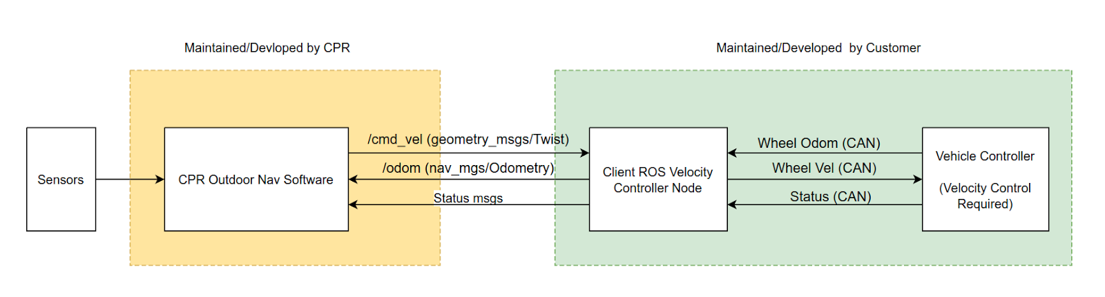
Interconnection between OutdoorNav Software and UGV Controller
A UGV must meet all of the requirements below to enable integration with OutdoorNav Software.
UGV moves forward when OutdoorNav Computer publishes:
$ rostopic pub -r 10 /platform_control/cmd_vel/ geometry_msgs/Twist "linear:
  x: 0.5
  y: 0.0
  z: 0.0
angular:
  x: 0.0
  y: 0.0
  z: 0.0"
UGV moves backward when OutdoorNav Computer publishes:
$ rostopic pub -r 10 /platform_control/cmd_vel/ geometry_msgs/Twist "linear:
  x: -0.5
  y: 0.0
  z: 0.0
angular:
  x: 0.0
  y: 0.0
  z: 0.0"
UGV turns clockwise when the OutdoorNav Computer publishes:
$ rostopic pub -r 10 /platform_control/cmd_vel/ geometry_msgs/Twist "linear:
  x: 0.0
  y: 0.0
  z: 0.0
angular:
  x: 0.0
  y: 0.0
  z: -0.5"
UGV turns counterclockwise when the OutdoorNav Computer publishes:
$ rostopic pub -r 10 /platform_control/cmd_vel/ geometry_msgs/Twist "linear:
  x: 0.0
  y: 0.0
  z: 0.0
angular:
  x: 0.0
  y: 0.0
  z: 0.5"
UGV’s model is visible in rviz when entering the following command on the UGV’s computer:
$ roslaunch platform_viz view_robot.launch
All “Required” Platform API are present when the following command is entered on the OutdoorNav Computer:
$ rostopic list
UGV’s wheel odometry is visible when the following command is entered on the OutdoorNav Computer:
$ rostopic echo platform_velocity_controller/odom
An example message from a Clearpath Robotics Warthog is shown below:
header:
  seq: 409289
  stamp:
    secs: 1634329699
    nsecs: 531439978
  frame_id: "odom"
child_frame_id: "base_link"
pose:
  pose:
    position:
      x: 0.0
      y: 0.0
      z: 0.0
    orientation:
      x: 0.0
      y: 0.0
      z: 0.0
      w: 0.0
  covariance: [0.001, 0.0, 0.0, 0.0, 0.0, 0.0, 0.0, 0.001, 0.0, 0.0, 0.0, 0.0, 0.0, 0.0,
      1000000.0, 0.0, 0.0, 0.0, 0.0, 0.0, 0.0, 1000000.0, 0.0, 0.0, 0.0, 0.0, 0.0, 0.0,
      1000000.0, 0.0, 0.0, 0.0, 0.0, 0.0, 0.0, 0.03]
twist:
  twist:
    linear:
      x: 0.0
      y: 0.0
      z: 0.0
    angular:
      x: 0.0
      y: 0.0
      z: 0.0
  covariance: [0.001, 0.0, 0.0, 0.0, 0.0, 0.0, 0.0, 0.001, 0.0, 0.0, 0.0, 0.0, 0.0, 0.0,
      0.001, 0.0, 0.0, 0.0, 0.0, 0.0, 0.0, 1000000.0, 0.0, 0.0, 0.0, 0.0, 0.0, 0.0,
      1000000.0, 0.0, 0.0, 0.0, 0.0, 0.0, 0.0, 0.03]
UGV’s e-stop status is visible when the following command is entered on the OutdoorNav Computer:
$ rostopic echo platform_msgs/status
An example message from a Clearpath Robotics Warthog is shown below, notice
stop_engaged: Truewhen the UGV is in an e-stopped state:header: seq: 0 stamp: secs: 1634330651 nsecs: 351159135 frame_id: '' hardware_id: "0.0.4" mcu_uptime: secs: 21496 nsecs: 0 mcu_temperature: 25.0 stop_engaged: True measured_battery: 53.9395599365 measured_48v: 53.9362373352 measured_24v: 23.9267425537 measured_12v: 12.0498123169 current_battery: -0.787658691406 current_48v: -1.0 current_24v: 0.240889504552 current_12v: 0.0445596463978 current_computer: 0.0410317406058 current_battery_peak: 0.0 total_power_consumed: 0.0
Odometry Performance Requirements
A UGV must meet all of the requirements below to enable integration with OutdoorNav Software.
UGV achieves accurate x-direction position when moving 5 meters forward:
Record the current UGV odometry from ROS. (It is easier if you restart the ROS controller node so that the odometry values become 0.)
Drive the UGV forward in a straight line at 0.5 m/s. To make sure that no angular velocity command is inserted, you may use terminal commands rather than manually driving the robot by joystick.
$ rostopic pub -r 10 /platform_control/cmd_vel/ geometry_msgs/Twist "linear:
  x: 0.5
  y: 0.0
  z: 0.0
angular:
  x: 0.0
  y: 0.0
  z: 0.0"
Stop the UGV at a finish line that you marked on the floor 5.0 meters from the start line.
Record the new value of the wheel odometry from ROS.
Calculate the accuracy by comparing the ground truth and the reported value of wheel odometry.
Record the resulting ROS reported distance travelled in meters.
Repeat the steps above so that you have 3 sets of measuremennts.
Confirm that the ROS reported distance travelled is between 4.75 and 5.25 meters for each of the 3 measurements.
UGV achieves accurate x-direction position when moving 5 meters backward:
Record the current UGV odometry from ROS. (It is easier if you restart the ROS controller node so that the odometry values become 0.)
Drive the UGV backward in a straight line at 0.5 m/s. To make sure that no angular velocity command is inserted, you may use terminal commands rather than manually driving the robot by joystick.
$ rostopic pub -r 10 /platform_control/cmd_vel/ geometry_msgs/Twist "linear:
  x: -0.5
  y: 0.0
  z: 0.0
angular:
  x: 0.0
  y: 0.0
  z: 0.0"
Stop the UGV at a finish line that you marked on the floor 5.0 meters from the start line.
Record the new value of the wheel odometry from ROS.
Calculate the accuracy by comparing the ground truth and the reported value of wheel odometry.
Record the resulting ROS reported distance travelled in meters.
Repeat the steps above so that you have 3 sets of measuremennts.
Confirm that the ROS reported distance travelled is between 4.75 and 5.25 meters for each of the 3 measurements. Confirm also that the reported distance travelled (per ROS) is negative for this backward test (whereas it was positive for the forward test).
UGV achieves accurate z-rotation position (yaw) +360°:
Record the current UGV Odometry from ROS. (It is easier if you restart the ROS controller node so that the Odometry values become 0).
Turn the UGV counterclockwise (+Z). To make sure that no linear velocity command is inserted, you may use terminal commands rather than manually driving the robot by joystick.
$ rostopic pub -r 10 /platform_control/cmd_vel/ geometry_msgs/Twist "linear:
  x: 0.0
  y: 0.0
  z: 0.0
angular:
  x: 0.0
  y: 0.0
  z: 0.5"
Stop the UGV at a finish position that you marked on the floor 360° counterclockwise from the start position.
Record the new value of the wheel odometry from ROS.
Record the resulting ROS reported angle travelled in degrees. Since the yaw value in wheel odom topic is in quaternion format, you will need to transform them to Euler angles.
Repeat the steps above so that you have 3 sets of measuremennts.
Confirm the ROS reported angle travelled is between 342 and 378° for each of the 3 measurements.
UGV achieves accurate z-rotation position (yaw) -360°:
Record the current UGV Odometry from ROS. (It is easier if you restart the ROS controller node so that the Odometry values become 0).
Turn the UGV clockwise (-Z). To make sure that no linear velocity command is inserted, you may use terminal commands rather than manually driving the robot by joystick.
$ rostopic pub -r 10 /platform_control/cmd_vel/ geometry_msgs/Twist "linear:
  x: 0.0
  y: 0.0
  z: 0.0
angular:
  x: 0.0
  y: 0.0
  z: 0.5"
Stop the UGV at a finish position that you marked on the floor 360° clockwise from the start position.
Record the new value of the wheel odometry from ROS. Since the yaw value in wheel odom topic is in quaternion format, you will need to transform them to Euler angles.
Record the resulting ROS reported angle travelled in degrees.
Repeat the steps above so that you have 3 sets of measuremennts.
Confirm the ROS reported angle travelled is between -342 and -378° for each of the 3 measurements.
Command the UGV to travel at 0.3 m/s. After 3 seconds, confirm that the ROS-measured wheel velocity is between 0.285 and 0.315 m/s.