Web UI Overview
The Web User Interface (Web UI) provides a easy, graphical, means to control both manual and autonomous operation of your UGV. The following sections outline: the components and views of the UI, the details of operating in manual mode, and the details of operating in autonomous mode.
Main Components
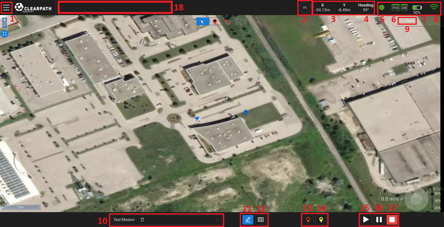
UI Main Components
Menu: A dropdown menu allowing the user to access the Dashboard (ie. Home), Settings, Status or Help pages.
Path Progress Meter: A meter indicating the percentage complete of a navigation Goal.
UGV Position: The UGV’s X and Y position in the world frame relative to the Datum.
UGV Heading: The UGV’s heading in the world frame.
Status Indicator: The status indicator will display information regarding various UGV status monitors such as the Emergency Stop, Surveying, etc. When the UGV is fully operational, the indicator will be green.
GPS Status Indicator: The GPS status indicators will display GPS signal accuracy for position (POS indicator) and heading (DIR indicator). Green indicators represent RTK accuracy and are currently required for accurate autonomous navigation. Noticeable oscillations may occur if the indicators are yellow. Red indicators mean no GPS signal and autonomous navigation missions should not be started.
Battery Life Indicator: The UGV’s battery life indicator.
Note
If the indicator is stuck at 50%, that means that your UGV does not have a supported battery management system and this indicator is not active.
Wireless Connection Indicator: The wireless connection indicator represents the signal strength between the wifi access point (typically the Base Station) and the UGV.
Views List: A dropdown list of available views, detailed later in this section. Some of the available views are Map, Camera and 3D views, etc.
Mission List: View the list of missions that Operator(s) have created.
Save Mission Button: Save the current mission. This will store the the current mission to the database.
Edit Mission Toggle: This toggle allows the user to start creating Goals for the current Mission. Once this button is enabled, the Waypoint Mode and Route Mode buttons will now be available for selection. When a Mission is started this toggle will be disabled (ie. the Operator will not be able to modify/add Goals).
Note
If the toggle is enabled while an autonomous mission is running, it will cancel the current mission.
Goal Panel Toggle: View list of Goals in the current mission.
Goal/Waypoint Buttons: The two waypoint indicator markers on the bottom bar allow the user to place either a Waypoint or Goal Point at the location of the UGV. These buttons work similarly to the route mode. The “Goal” button initiates a Goal Point and the “Waypoint” button extends the Goal. Pressing the “Goal” button again will start a new Goal.
Start Button: Start the current mission (ie. execute the list of enabled Goals sequentially).
Pause Button: Pause the current Goal. Pressing the start button while paused will continue the current mission.
Stop Button: Cancel the Goal or Task that is currently being executed. Pressing the start button while when stopped will restart the list of Goals in the current Mission.
Feedback Bar: The feedback bar will display information regarding the execution state of the navigation and of any Tasks being executed.
By opening the dropdown list “Views”, on the right side of the UI, the Operator can access the following views:
Map View
PTZ Camera View (if available)
Front/Back Camera View (if available)
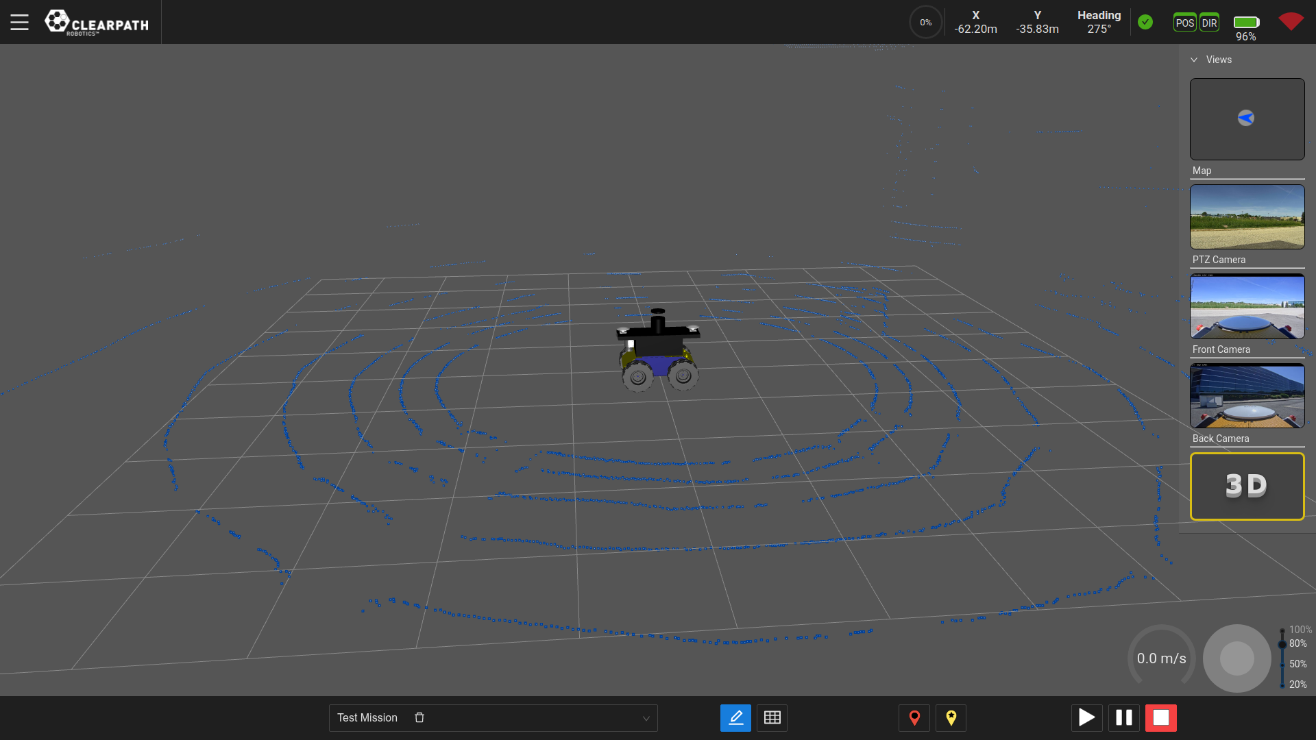
3D View
Map View
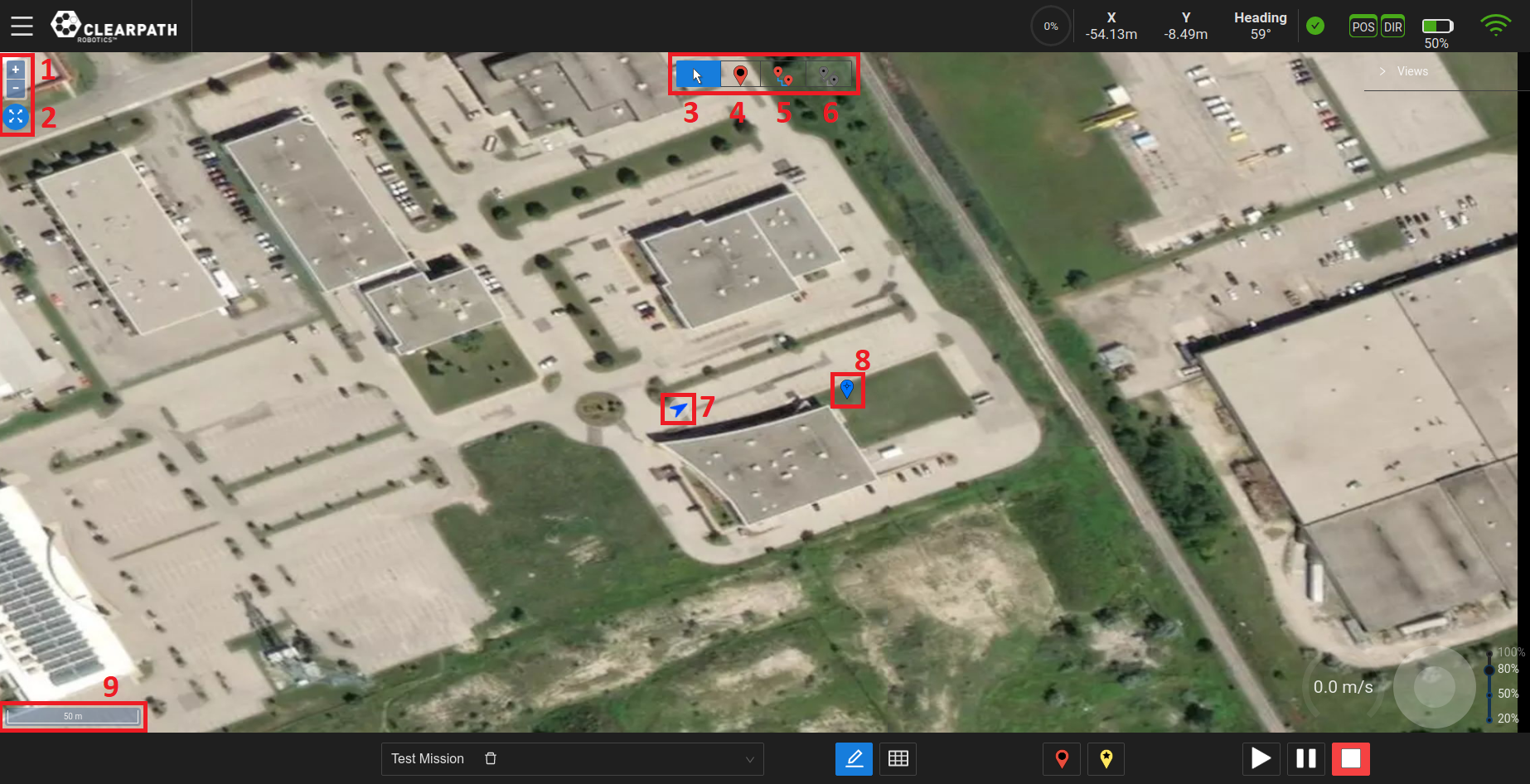
Map View
Zoom Buttons: These buttons allow the user to zoom in/out of the map levels.
Zoom-to-Fit Button: This button will zoom the map to where there is activity (ie. where the datum is set or where Waypoints have been set on the map.
Pointer Mode Button: This button allows the user to move the map and select point on the map to see their coordinate (lat/lon or x/y).
Waypoint Mode Button: This button allows the user to place Waypoints on the map. Users can also select existing Waypoints to modify/delete them.
Start Route Button: This button allows the user to create a route of Waypoints which will form a path from the UGV’s current position to the first point clicked to the last location clicked. As points are clicked on the map, the Waypoints are added sequentially to the Goal with the last point clicked being the Goal Point.
End Route Button: This button will finalize the Goal that is currently being created and allow the user to start creating a new Goal.
UGV: The blue arrow represents the UGV. Its location is its position in the world frame and its orientation is the heading in the world frame.
Datum: The blue Waypoint marker on the map view represents the location of the reference point (ie. (x,y)=(0,0)) of the world coordinate system. The world (ie. map) coordinate system is in the ENU convention.
Scale: The scale representing the ratio of a distance on the map to the corresponding distance on the ground.
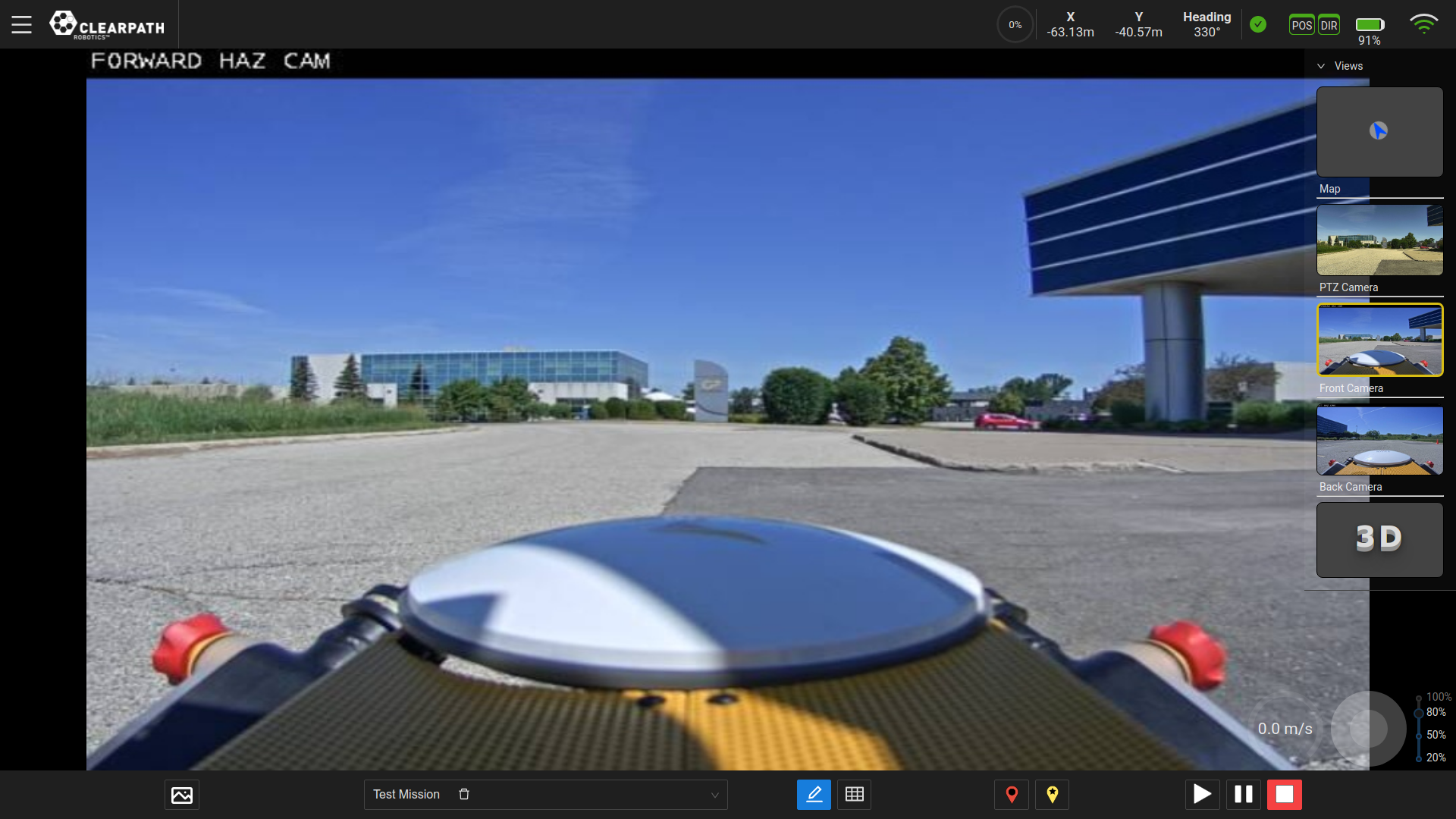
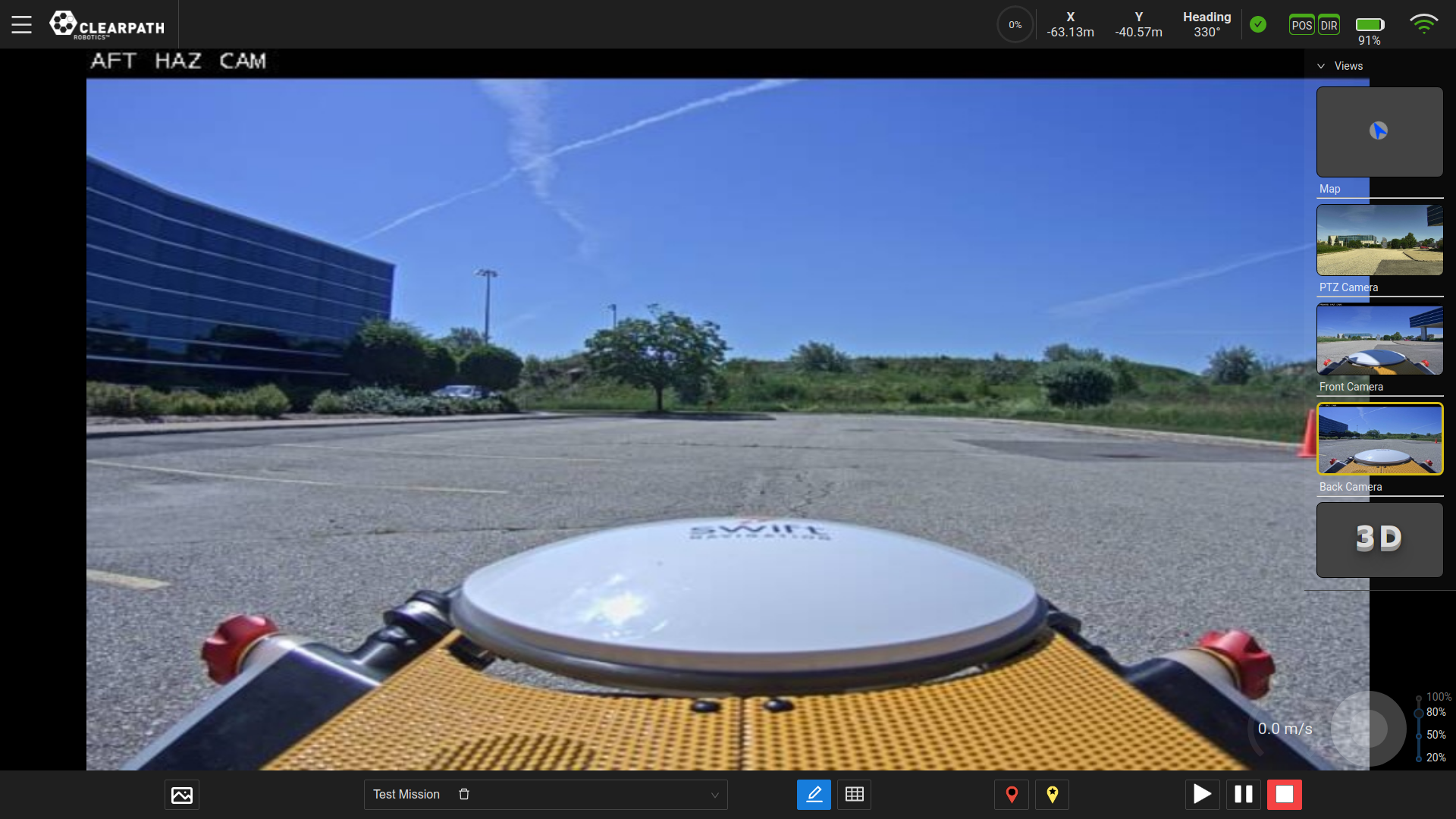
Camera Views
Note
If PTZ and/or Front/Back camera(s) are included on the UGV, their feeds can be viewed through the UI and the PTZ can be controlled through the UI. If not, there will not be any PTZ, Front/Back view(s) in the list of available views.
Pan-Tilt-Zoom (PTZ) View
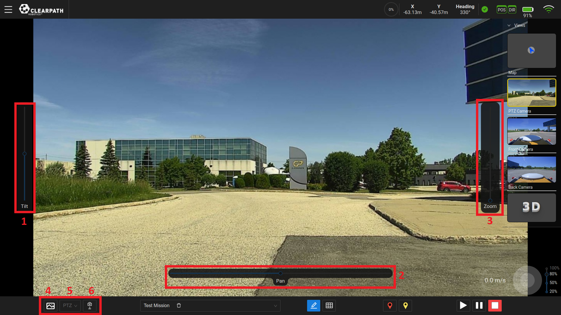
PTZ Camera View
Tilt Slider: The left slider can be used to tilt the camera in a vertical motion, (ie. upwards or downwards motion). By default, the slider is at its neutral (“zero”) position.
Pan Slider: The bottom slider can be used to pan/rotate the camera, (ie. rotational motion). By default, the slider is at its neutral (“zero”) position.
Zoom Slider: The right slider can be used to zoom the camera feed. By default, the slider is at its neutral (“zero”) position.
Save Image: Depending on the current camera view selected, this button will save an image to the computer/tablet running the UI. Images will be saved to the location in which your browser saves files.
Camera Positions List: Display the list of available camera positions that have been saved. These camera positions can be deleted from this list by clicking the “garbage can” icon beside the corresponding position.
Save Camera Position: This button will save the camera position to be used in the “Move PTZ” task. An example use case would be: #. Switch to the PTZ camera view.
Teleoperate the UGV to a location at which the user can inspect something.
Move the camera sliders to orient the camera such that it is looking at the inspection point.
Click the “Save Camera Position”.
When creating an autonomous mission to this inspection point, add the “Move PTZ” task to Goal.
Click the settings button beside the task and add the camera position related to the inspection point.