Navigation
Features
The OutdoorNav Software contains a set of features that can be enabled or disabled according
to your required application requirements. These features can be enabled or disabled through
the use of environment variables, which should be added to the /home/administrator/cpr_outdoornav_launch/cpr_autonomy.env.
The following table describes the available features, their default state and any additional
parameters that we expose that may also be included to tune the feature.
Feature |
Description |
|---|---|
Data Collection |
The data collection feature enabled the user to record rosbag data of the sensors, localization, and navigation components of OutdoorNav. If Environment Variable: |
Collision Avoidance |
Collision avoidance is the UGV’s ability to detect obstacles and stop/maneuver around the
obstacle without any collisions. If Environment Variable: |
Obstacle Avoidance Mode |
When collision avoidance is enabled, the UGV will behave in one of two ways according to the
obstacle avoidance mode. If set to Environment Variable: |
Continuous Planning |
The continuous planning feature allows the UGV to continuously monitor whether an obstacle is on the UGV’s path and replan around said obstacle smoothly without the need for stopping in front of the obstacle. If disabled, the UGV will come to a full stop in front of an obstacle and then replan around said obstacle. Environment Variable: |
Path Smoothing |
The path smoothing feature allow paths to be generated according to a specified turning radius. The default behaviour will generate point-to-point straight line paths. Environment Variable: |
Path Shifting |
The path shifting feature is designed to reduce the oscillation around the initial reference path if the UGV begins to deviate of said reference path. It is particularly useful for the Clearpath Robotics Warthog platform whose tires are incredibly pliable and results in unmodelled effects on the navigation. Environment Variable: |
Constrained Replanning |
The constrained replanning feature restricts the area in which replanning paths can be generated.
For example, if a Environment Variable: Use the |
Stop Distance |
The stop distance feature allows the UGV to stop a predefined distance away from obstacles. This is useful if a UGV cannot drive in reverse and needs the required room in front of it to replan around an obstacle. Environment Variable: Use the |
Delay Compensation |
The delay compensation feature is able to compensate for mechanical delay on UGVs where either the accelerator introduces delay into the linear velocity or the steering introduces delay in the angular velocity. This feature is not required for Clearpath Robotics UGVs as negligible delay is present in our system. Environment Variable: Use the |
Command Line Operation
By default the OutdoorNav Software, including the Navigation component, begins automatically when the system is powered on. This section outlines the commands that can be used by developers who are debugging the system or who want more precise control for managing the Navigation component.
Accessing the Shell in Docker Container
To access the shell in a Docker container for debugging (optionally replace onav-autonomy with
onav-web in the following command):
cd ~/cpr_outdoornav_launch/      # The directory with docker-compose.yaml
docker compose exec -it onav-autonomy bash
Validating TF Setup
Note
Sensor TF validation should only be required if the performance is noticeably poor, such as when the UGV drifts off of the planned path or oscillations occur around the path).
The coordinate transformation of the two GPS antennas, the IMU, the 2D and 3D Lidars to the base_link of the UGV should have already been set prior to receiving the UGV. However, ensure that they are set correctly.
The ROS coordinate frame base_link, shown in the figure below, is located at the center of the bottom plate of the UGV. The environment variables below should be taken with respect to this coordinate frame. The X axis is in red (and pointing towards the front of the UGV), Y in green (pointing towards the left of the UGV) and Z in blue (pointing towards the sky).
You can check the current value of the environment variables by running the following (and setting <variable_name> to the names listed in the table below).
printenv | grep <variable_name>
The environment variables for the position and orientation of each sensor are provided in the table below.
Environment Variable |
Function |
|---|---|
POSITION_GPS_XYZ |
[X,Y,Z] position, in meters, of the position (rear) GPS antenna with respect to the base_link coordinate frame |
POSITION_GPS_RPY |
[Roll,Pitch,Yaw], in radians, of the position (rear) GPS antenna with respect to the base_link coordinate frame. |
HEADING_GPS_XYZ |
[X,Y,Z] position, in meters, of the heading (front) GPS antenna with respect to the base_link coordinate frame. |
HEADING_GPS_RPY |
[Roll,Pitch,Yaw], in radians, of the heading (front) GPS antenna with respect to the base_link coordinate frame. |
MICROSTRAIN_XYZ |
[X,Y,Z] position, in meters, of the IMU with respect to the base_link coordinate frame. |
MICROSTRAIN_RPY |
[Roll,Pitch,Yaw], in radians, of the IMU with respect to the base_link coordinate frame. |
LIDAR_XYZ |
[X,Y,Z] position, in meters, of the 3D Lidar with respect to the base_link coordinate frame. |
LIDAR_RPY |
[Roll,Pitch,Yaw], in radians, of the 3D Lidar with respect to the base_link coordinate frame. |
LASER_XYZ |
[X,Y,Z] position, in meters, of the 2D Lidar with respect to the base_link coordinate frame. |
LASER_RPY |
[Roll,Pitch,Yaw], in radians, of the 2D Lidar with respect to the base_link coordinate frame. |
Note
When the printed Y axis on the IMU is pointing towards the front of the robot (i.e., aligned to X axis of base_link), MICROSTRAIN_RPY = [0, 0, 0].
Warning
If you decide to move any of these sensors, you must modify these variables accordingly.
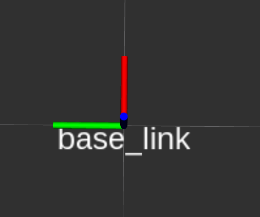
base_link coordinate frame